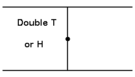
(Description last updated 2009-03-31) This vertical can be used on all the HF bands, efficiency is good on 40m and up, less on 80m and of course very low on 160m. Status: Built and erected in May 2008, currently in use. Recently, when movinginto a rented upper story of a duplex, I was faced with the challengeof putting up an antenna that would not offend my new landlord toomuch. While it has been demonstrated that elevated verticallypolarized antennas perform worse than their horizontally polarizedcounterparts (see ARRL Antenna Handbook, 19th ed, chapter: "The effectsof Ground"), one's choices may be limited by practical circumstance. Also, lately I have been able to compare the antenna described in thisarticle to a full size horizontal 1/2 wave 20m dipole, elevated 9m(30'). On average I do not notice much of a difference between the twoantennas. Sometimes one is better, sometimes the other, based on thepolarization and direction/elevation angle of the incoming signal. Back to the subject athand. LB Cebik, W4RNL (SK) and others have demonstrated that loadedverticals in a Double T configuration can be considerably shortenedwithout significant loss of performance. Modeling with EZNEC confirmsthis.
As my only choice ofmounting an outdoors antenna was to attach it to a balcony banister, mybest choice seemed to be a self contained antenna that wouldn't need acounterpoise, this seemed to be worth exploring further. A market search revealedtwo antennas being sold which were based on this exact approach. Bothantenna makers sold their antennas with a multiband option, utilizing areasonably efficient switchable hairpin match. However, when studyingthese antennas, a few thoughts struck me:
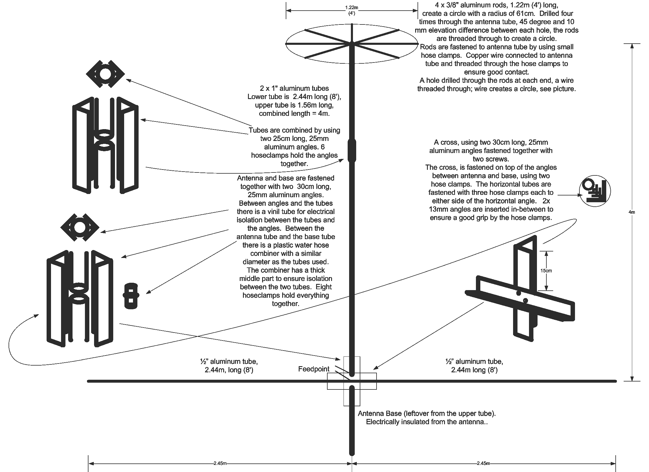
Firstly the very highprice, I would surely be able to build myself something similar for afraction of the price these antennas were being sold at. Secondly, why centerfeed the antenna and have an unsightly coax hang down from the middleof it. One manufacturer tries to explain this at length, concludingthat this gives some extra dBs. However the logic appears to beseriously flawed. Offset feeding the antenna should yield exactly thesame results as a symmetrical feed, if the antenna is fed and matchedto properly (balanced + impedance match). A double T antenna wasmodeled in EZNEC, with both centre feed and offset feed, confirmingthat they were indeed exactly the same. Moreover, while the centrefeed would yield an impedance considerably lower than 50 ohm (the lowerthe smaller the antenna is), an offset feed would yield a higherimpedance, closer to 50 ohm, an extra added bonus. Thirdly, while walkingthrough the local hardware store and taking inventory of the aluminumtubing they had available, I realised that a double-T vertical antennaconstruction might be impractical as it was rather top-heavy, why notmake the whole antenna assymmetrical, that it would be better to trimdown the wind load of the top section. The following design shows theend result, guided by the material I found in the hardware store. Again, despite some of the writeup referred to above, it has no effecton its effectiveness whether the antenna is center fed and symmetricalor "bottom" fed and assymmetrical in its dimensions. This can easilybe demonstrated by playing with the dimensions in EZNEC or otherantenna modeling software. What matters is the antennas overallelectrical dimensions, the characteristics of the ground (reflectingthe radiowaves, thus introducing losses) and the elevation of theantenna and its current maximum point above the ground.
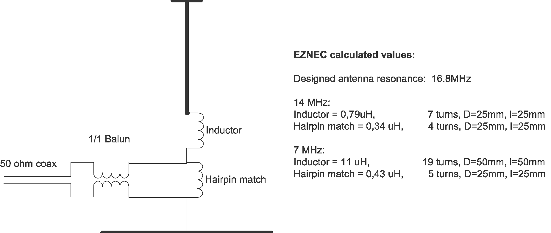
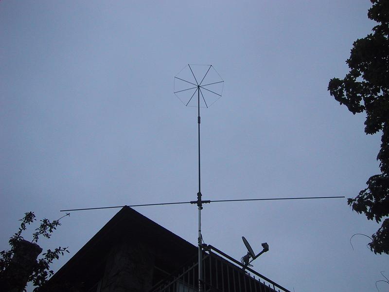
(click on picture to enlarge) The design was based on acouple of basic criteria. Resonance at or slightly above 20m, to becompensated by a hairpin match if/as necessary, and elevation ofantenna not to exceed 4m. Dimensions of the antenna were decidedotherwise by the length of the material purchased (Aluminum tubes camein lengths of 8 feet and aluminum rods in lengths of 4 feet). Thisdesign was modeled in EZNEC, which calculated theresonance frequency to be 16.8 MHz with the material and dimensionsselected. This suited me fine. With these dimensions EZNEC predictedno performance loss of consequence on 20m when compared with a fullsize dipole with its current maximum (center) at the same elevationabove ground, and quite acceptable gain on 40m as well. Using EZNECagain, I designed a hairpin match for 20 and 40m:
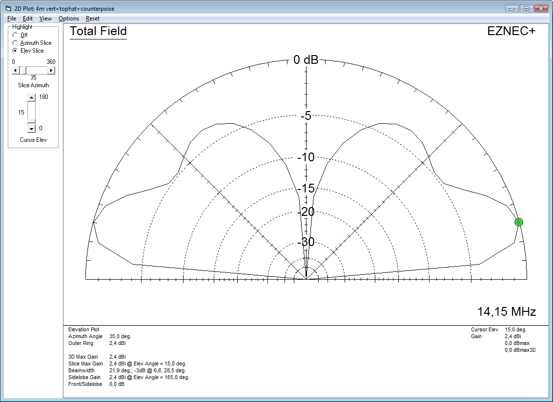
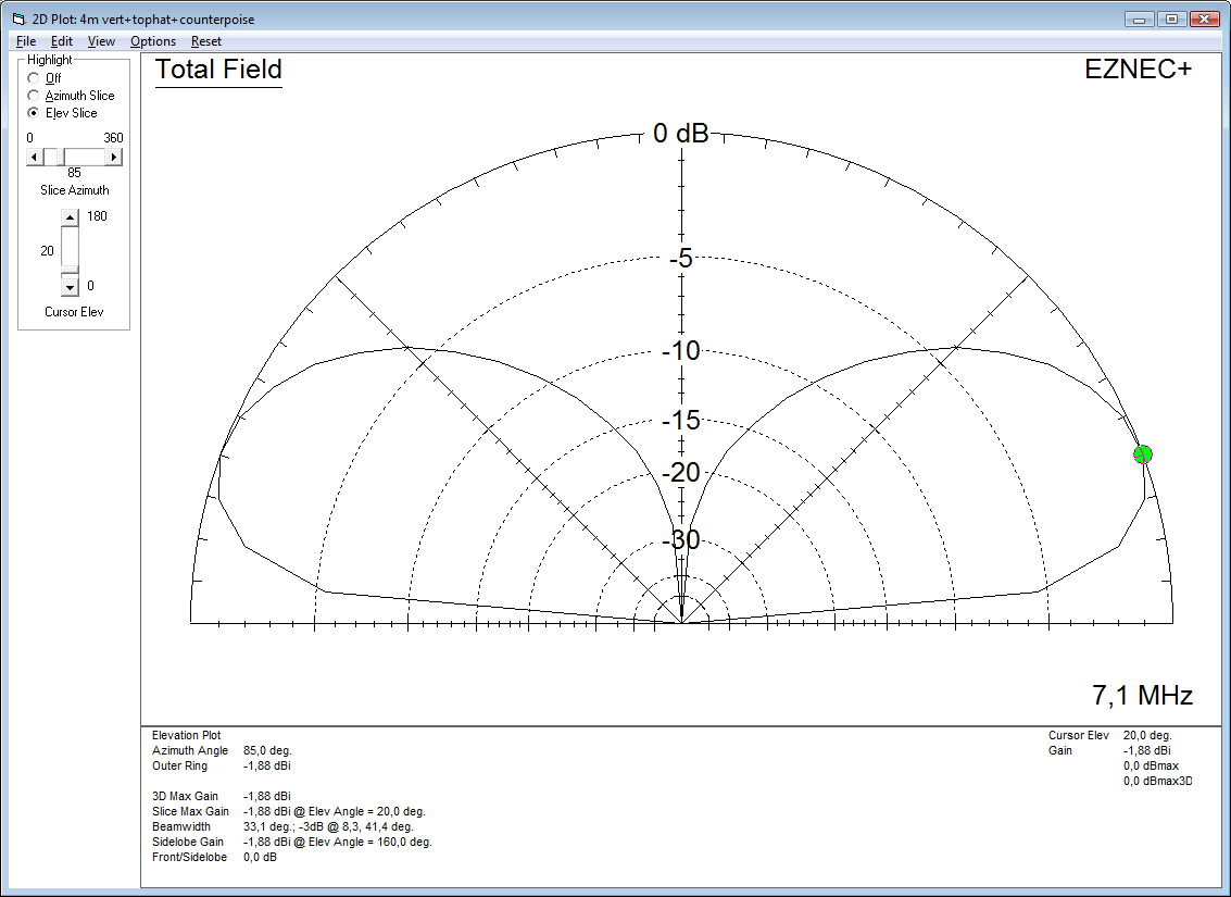
(click on picture to enlarge) Here are the EZNEC predicted radiation patterns for 20m and 40m: (click on picture to enlarge) (click on picture to enlarge) To try to make a longstory approach its end, the antenna was assembled for a total cost ofprobably less than $100, spray painted black for less visibility to theneighbours and erected after dark :) The antenna has now been up for10 months, or since late May 2008.
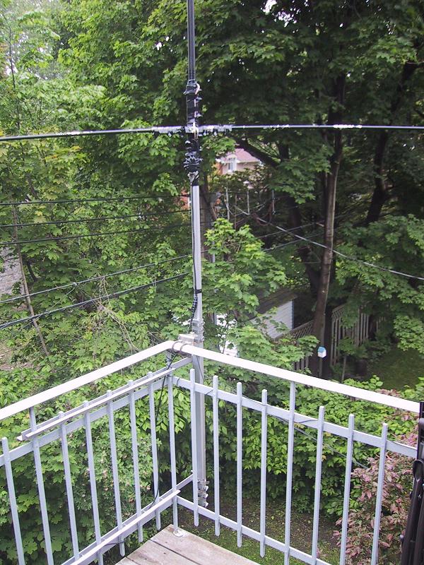
(click on picture to enlarge) (click on picture to enlarge) On this image, the Balun used is faintly visible, RG-58 wound through a Ferrite Toroid. Hairpin match was not used, see below. To put anend to this rather too long story: The antenna was erected. Itsresonant frequency was measured to be quite a bit lower than expected,or just below 20m. (Hairpin match depicted above not useable :) Thisis most likely due to the capacitive coupling in the aluminum anglebracketing method used to hold the vertical and the horizontal elementsas well as the base of the antenna together. Because of capacitivecoupling into the base, the balcony banister probably participates inthe antenna to some degree. The design could obviously be improved,but I very much doubt that this has a significantly detrimental effecton the performance of the antenna. A few centimeters were cut off ofeach end of the horizontal section for best resonance at 14 MHz. Dueto my inherently lazy nature, I ended up mounting an autotuner belowthe antenna, rather than building a band switchable matching circuit. With the autotuner, the antenna can be tuned from 160 through 6m,efficiency is of course degraded at 80 and 160m, but the antennaappears to be quite usable on 80m.
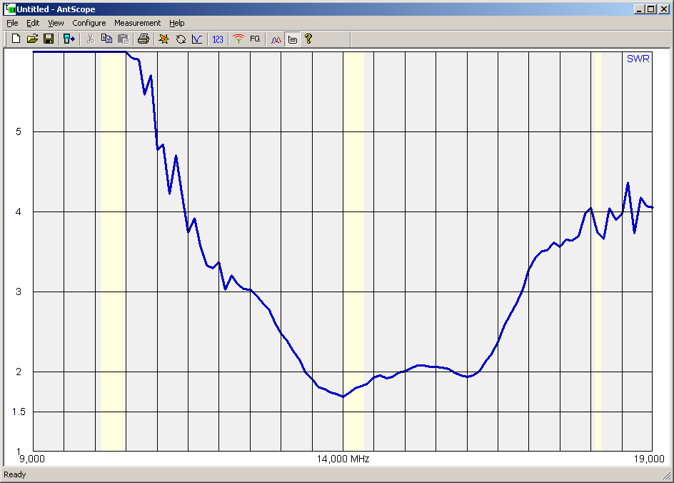
An SWR measurement on 20m through an inactive autotuner and 10m of RG58 is shown here: (click on picture to enlarge) Thismeasurement was taken today (2009-03-21) with the autotuner in thecircuit, but turned off. Note that I couldn't find the originalmeasurement from 10 months ago, taken without the autotuner in thecircuit. Although inactive, the autotuner appears to worsen theSWR noticeably in the 20m band where it is not needed. If my memoryisn't too far off, the original measurement indicated an SWR of about1.2 to 1.4 across the 20m band. In any case, as can be seen, thebandwidth of the antenna is very high. This is not due to any lossyelements, but due to the top and bottom loading incidentally having themakings of a decent emulation of a wide band conical antenna (disccone, duo cone). Not a bad bonus.
 |
|